Mark Hofmeister
Movable Math
Class
Location
Pittsburgh, PA
Year
2021
Resources

Movable math is a solution that allows students to learn fundamental algebra through the exploration of the environment of an equation. It utilizes physical pieces connected to software that updates in real-time with the actions of the student.
I led the hardware development of this project, including the physical design and printing of the board layers, electrical connection wiring, and template design.
More information can be found below, as well as on our website, linked in the "External Links" tab.
How Does It Work, and WHy does it work this way?

The device is predicated on changing resistance by adding resistors in parallel. In the system diagram, you can see that the voltage read across the reference resistor, labeled with a V, will change as more resistors are added to the empty circles of the diagram, as they are wired in parallel.
The 5 circles in the diagram represent one column. Adding a piece to a column will change the resistance, changing the reference voltage that is recorded by an Arduino Mega through analog serial ports. The software then uses this data to make the appropriate change to the equation display.
Adding pieces changes resistance by directing current through a resistor embedded in each piece. We ideated many mechanical designs but settled on a cylindrical "chess piece" style design.
Not only does this make the fabrication of each piece much easier, but it prevents pieces from rolling around and causing teachers and instructors a nightmare of picking hundreds of little pieces up off the floor.
We built upon the idea of making this a simple device for both students and teachers by including the carrying case, which allows students to clean up themselves and store everything in one compact location.


I did eventually complete the wiring, however - there are over 60 individual wires there and 100+ solder joints. Contained in these channels are the 5-volt channels (red), resistors, voltage divider paths (green), and ground wires.
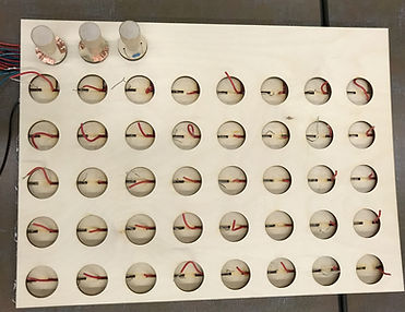
Also shown is a much clearer picture of the circular piece hole board superimposed on the trace board, also laser cut from 1/4'' thick plywood. The wires have been trimmed a bit and organized, and you can see the first iteration of the pieces stationed above the holes, along with the resistors and copper tape to complete a connection.
This is a photo of the bottom layer trace board, laser cut out of 1/4'' thick plywood. The channels are 1.5 mm across - barely large enough for the laser cutter to recognize.
I learned that it may have been smarter to scale up the size of the whole board, remove the vertical channel dividers, and make the channels a bit wider. It definitely made wiring up the board a bit more challenging and take much more time.


We hooked the wires up to an Arduino Mega in connected to a screwboard, and tested the voltage readings on the Arduino IDE. The We had issues with reliable electrical connections between the pieces and the board, which resulted in faulty or unrecognized voltage changes.
I decided that we'd need to add another force between the pieces and the holes - whether it be weighting the pieces or something more subtle.

We tried everything - new copper tape, conductive paint, increased conductive surface area - but the solution turned out to be magnets.
I began with simple refrigerator-style magnets, shown on the left. These were large, bulky, and too weak; they hindered our ability to maintain a connection.
We switched to neodymium magnets, shown to the right. There are 200 in that picture - 180 of which were incorporated in our design.


A vinyl-cut sticker and one full day of gluing and foil wrapping later, we had our finalized board design. The tiny magnets allow a strong electrical connection with minimal impact on the bulkiness of using the product, ensuring that it is a smooth experience for students exploring algebra.