Mark Hofmeister

As an avid cook, it's important to me to have a wide variety of fresh herbs to bolster my dishes. Storebought herbs, however, spoil quickly, lose freshness, and add up cost-wise. I decided to plant my own herbs in my garden to get the biggest and boldest variety of herbal flavors.
The downside of an herb garden is that it requires constant maintenance, mostly in the form of watering. Timed watering valves exist, but a set timer is not the best way to water plants amidst so many environmental variables such as daylight, heat, and natural precipitation, rendering the "automatic" aspects of the system nearly useless.
ShowHerb is an automated garden watering system that determines watering frequency via soil moisture levels rather than time. Additionally, ShowHerb integrates light, rain, and temperature sensors to tune the watering frequency and intensity, resulting in a much more precise and hands-free method to keep plants healthy.
How Does It Work, and Why does it work this way?
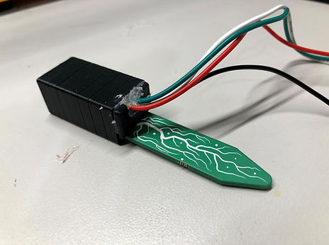
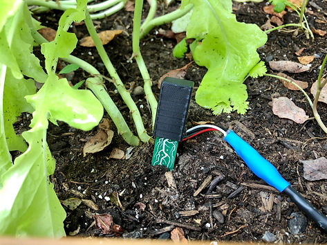
I used Adafruit's STEMMA Soil Sensors to measure the moistness of the soil. This is due to the reliability of capacitive measurements over resistive, along with their compact nature. I 3D printed a protective casing for the exposed circuitry on the sensors, as they would need to stay functional within the elements of the outdoors. The wires are exposed through a small hole in the plug, sealed off with hot glue.

One of my goals with this project is to create a system that can easily work with more soil sensors added. The STEMMA sensors work with the I2C communication protocol, so they are assigned the same address from the factory. As the sensor hardware only allows 4 different address options, I purchased an I2C Multiplexer to allow up to 8 sensors to be used with the same address. With this open bus space, I can theoretically use up to 32 sensors in my garden.
See it in action
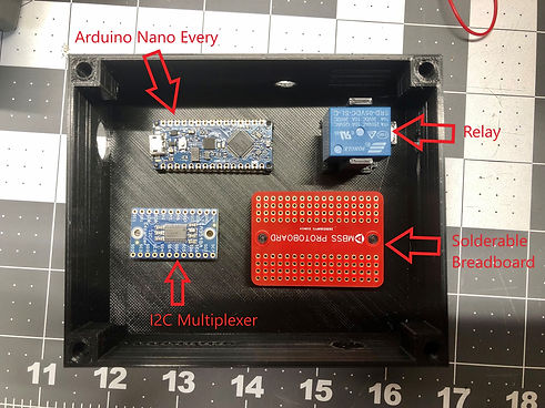
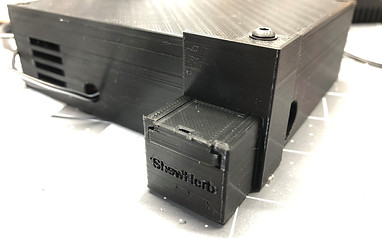
To keep my central circuitry layout consistent and organized, I designed and printed a control Box to house the controlling components. Each device rests on pins or support structures that allow easy wiring/soldering access, along with precision-sized holes to accommodate power source connections or wires connected to other sensors.
Through the use of knurled threaded inserts and a soldering iron, I added a cover plate that can easily be removed by a hex key. This further eases future additions of more sensors.


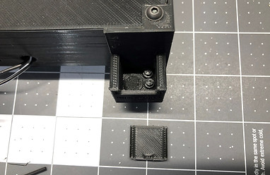
Additionally, I printed plugs that cover unused holes in the control box. This is to mitigate dust and micro-debris that might interfere with or break delicate components inside.
Unused plugs are stored in a small container that connects to the box through an existing screw. The container is also 3D printed.
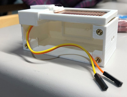
The rain and light sensors had to be housed separately, as they would interface directly with nature. I 3D printed a housing with some design concepts related to the control box, but with a more rugged structure due to its element exposure.
The final housing consisted of 3 pieces:
-
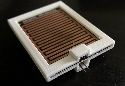
Rain sensor conductive interface shield
-
Photocell lead shield
-
Rain sensor comparator PCB housing
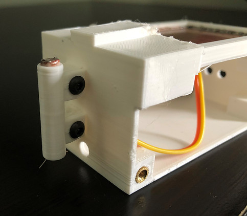
The top right image shows the shield that exposes only the rain sensor's conductive face to the sky; the bottom right photo shows the conductive interface shield docked in the comparator PCB's housing. The PCB's housing is accessed via hex key due to more threaded inserts on the PCB housing's side.
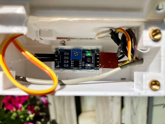
The comparator PCB sits on the wall of the housing, nested in a "shelf" of sorts. This accomplishes two goals: It allows for easy access to the PCB's potentiometer to adjust sensitivity, and it keeps the PCB off the ground plane of the housing in case standing water were to leak through outer seals.
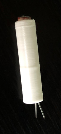
The photocell casing began as a cylindrical tubing with holes to feed leads through as a means to protect the bulk of exposed metal from the elements. However, the leads were not well separated from each other and the tiny photocell casing would be a challenge to mount and wire.
To solve this, I reprinted a new casing with a PLA divider in between the leads and holes to attach to more threaded inserts in the side of the rain sensor housing, as seen on the right. This provides a secure angle to expose the photocell to nature and simplified both wiring and mounting.
The housing ended up being mounted on the outside of my garage, with the wiring travelling through drilled and sealed holes.
All that was left to do was mount, wire, and solder final components through the garage walls.
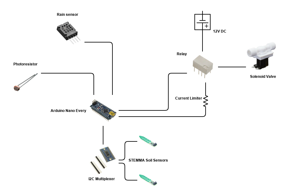
Below is a system diagram showing the hardware that is connected in this project, along with a flowchart explaining the code.