Mark Hofmeister
AoM IoT Bit
Client
Location
Pittsburgh, PA
Year
2021-Present
Resources

BOM
User Guide
I'm a TA for a course in the University of Pittsburgh's engineering department called "The Art of Making," or "AoM" for short. The core of the course is teaching engineering students the fundamental tenets of design thinking, which is a mode of thinking that prioritizes user-centric design. We love prototyping and user-testing ideas at "the speed of thought" so that we can fail fast and iterate quickly.
To aid students in their rapid prototyping process, we deploy a myriad of technology platforms, one of which is a series of snap electronics called LittleBits. One bit in particular, the CloudBit, allowed students to quickly connect a Littlebits system to the internet, enabling "Internet of Things" functionality. Unfortunately, Littlebits ceased support for the bit and the cloud backend that it connected to.
To ensure students maintained the ability to prototype the functionality of Internet connectivity, the TA team was tasked with constructing a proprietary solution to interface the Littlebits ecosystem with the Internet. I led the charge to drive that cognitive ideal into reality.
Problem Statement
In the Art of Making, we present a myriad of technologies and skills in parallel with student design sprints and capstone projects to empower them to build the best possible solution to real problems. One of these technology platforms is littleBits, an ecosystem of circuit modules that magnetically snap together. littleBits makes prototyping complicated cyber-physical systems incredibly rapid. In practice of "show, don't tell," I'll let Sphero show you more about the ecosystem:
One of the most sophisticated littleBits was the "CloudBit," which allowed a littleBits circuit to interface with the internet. Snapping a CloudBit into a LittleBits circuit made it instantly capable of sending and receiving data from the littleBits cloud, accessible from a desktop computer or the littleBits mobile app.

The CloudBit was tremendously useful for prototyping Internet of Things (IoT) functionality, which mesh physical "things" (lights, motors, speakers) to cyber environments, like apps and cloud data processing. Unfortunately, littleBits discontinued the CloudBit in 2018 and the support for the littleBits cloud in 2021. Left without a way to prototype IoT functionality, the AoM instructional staff asked ourselves:
How might we create a solution to rapidly simulate IoT functionality in a way that seamlessly integrates with the littleBits ecosystem?
Ideation
There's no shortage of microcontrollers, processors, and hobbyist development devices that can connect to a cloud wirelessly. There's also no shortage of cloud services that have countless hooks to talk to the APIs of other services. Our constraints for this project are particularly unique, however.
Our Solution Must
-
Support Rapid Prototyping - While the newest & fastest controller might wirelessly turn a servo on *that* much faster, it wouldn't do much good if it takes weeks to set up. We're looking to fail fast with rough zeroth-order approximations of functionality.
-
Be usable for those with minimal electronics experience - The Art of Making is a class that any Pitt student can take, not just electrical and computer engineers. Therefore, our solution should require as little overhead initialization as possible for all that might choose to use it.
-
Support "Black Box" Functionality - A culmination of the last two points, we want our solution to be "Plug n' Play" - i.e. anyone can add our solution to a littleBits circuit and quickly initialize it so the circuit's signals can be connected to the internet.
-
Support both Inputs and Outputs - i.e., we want our solution to both send and receive data from a cloud.
-
Be maintainable by future AoM instructional staff members - The current TA team isn't around forever. If we want our work to be used by generations to come, it must be maintained by those that succeed us.
We decided to make our own "bit" - i.e. create a device that interfaces directly with the littleBits magnetic connectors. Our bit would be powered by the littleBits power source, so it could be completely dependent on only the littleBits ecosystem.
We first considered the wireless communication protocol to use. We considered WiFi, Bluetooth, LoRa WAN, and a direct ethernet connection.
Bluetooth is quick to connect, but its range is limited. We also deploy the littleBits Wireless transmitter and receivers, which use Bluetooth and are for a totally different use case.
LoRa WaN is a nice technology, but we were completely unfamiliar with it and were not concerned with power consumption.
Ethernet is fast, but requiring an ethernet connection would severely limit the placement and therefore use case of the IoT Bit, so we opted to use WiFi.


We then considered the hardware necessary to interface littleBits with WiFi. It had to be WiFi-capable in a small form factor, and able to be easily debugged for maintenance years in the future. We looked at Arduino, Raspberry Pi, and other IoT-centric obscure platforms.
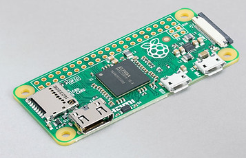
While a Raspberry Pi is the token internet board for hobbyist projects, it was a bit overkill for this project. We were seeking to send one digital signal, and we didn't need all of the processing power or peripherals that Pis offer. We also couldn't get one due to supply chain issues.
We did want to use something that we knew well, however - so we chose the Arduino platform. Specifically, we chose to use the Arduino MKR WiFi1010 board, which hosts WiFi on a tiny board.

Arduino MKR WiFi1010
Finally, we selected a cloud platform. Ideally, we'd like to create a proprietary backend cloud service, but we wanted to get a functioning device for user testing before taking on such a challenge. We decided to test on Arduino IoT Cloud, Adafruit IO, and Amazon's AWS.
AWS is the most sophisticated platform that we looked at but had a few too many bells and whistles for our application. There was also too steep a learning curve for new users doing rapid prototyping.
Arduino IoT Cloud is quite hobbyist-friendly, but the free version is quite limiting and I've personally had poor experiences with the service in the past when I was developing ShowHerb.
Adafruit's cloud service has free account permissions that are lenient enough for our application, has a simple UI, and integrates easily with IFTTT, which will be discussed in more detail below. Therefore, we decided to use Adafruit IO.


Breadboard Prototype
Before I dove into CAD or soldering, I wanted to test the nature of the MKR WiFi1010's connection to the Adafruit IO cloud. I was able to both send data to and receive data from a test Adafruit IO cloud feed.
I connected the Adafruit IO feed to "If This Then That (IFTTT)," a website that allows you to chain together API functionality from a myriad of web-based services. For example, I was able to connect Adafruit IO to my Google Calendar account and create a Google calendar event every time Adaafruit IO received a "HIGH" signal in the feed, which was uploaded from the MKR WiFi1010 every time I pressed a button on the breadboard.

Below is a video demonstrating this working.

On the left is a "bitSnap," which is how littleBits modules snap and electrically connect to one another. We decided to run the Vcc and Gnd busses through the Arduino for power so that the IoT Bit could be placed in series with other littleBits. While the signal bus can carry analog and PWM signals, we would only work with posting and getting digital signals from the cloud - but PWM and analog signals are future opportunities.
We purchased some of Arduino's MKR MEM Shields to mount on top of the MKR WiFi1010s, which have a microSD card reader wired to the appropriate pins. This allowed us to input credentials necessary for connecting to WiFi and for sending HTTP requests to Adafruit IO, and abstracts away much of the messy Arduino code. You will see that we rolled out the IoT bit to students with this SD card reading as part of the "black box" functionality.
One of my fellow TAs Issam Abushaban rigged up a breadboard that was powered by and could send signals to and from littleBits hardware. We also added the ability to switch device functionality in real time. By flipping one switch or the other, one could "post" the incoming littleBits digital signal to the Adafruit IO feed or "get" the most recent digital value in the Adafruit IO feed and write that signal to a littleBits signal output.

Enclosure & TUI Design,
Preliminary User Testing
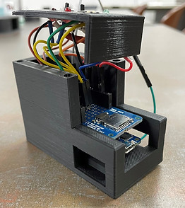
Once we accomplished a fully functioning breadboard prototype, I moved to design a compact enclosure. This enclosure had to be durable, fairly light, able to mechanically and electrically integrate with littleBits, and abstract as much of the unnecessary circuitry as possible with a simple tangible user interface (TUI.) I opted for a two-piece 3D-printed enclosure and heat-set threaded inserts. I'm very familiar with 3D printing, which supports all design requirements and allows for iteration.
On the right is the first iteration that I printed. It lacked proper cutouts to accept littleBits bitSnaps and had hole tolerances for TUI components slightly off. During the first round of user testing with fellow TAs, it became apparent that my enclosure could not actually "snap in" to littleBits modules easily or fit into the littleBits mounting boards.


I corrected these issues, shown in the rendering to the left. Notice how the orange bitSnaps protrude from the bottom of the enclosure now. I added some decals (to be implemented with colored Vinyl) and CAD models for the button, switches, and LEDs. I figured that it'd be easy to hot glue the components in the top and fit all of the wires underneath the top plate, but reality always thwarts the ideals of theory, as will be seen soon.
Here's a more detailed look at the TUI. This will come to be realized in atoms soon, but a representation in bits will do for now. Notice the ability of the IoT bit to be placed in series with a chain of connected littleBits modules.

Firmware Flow
We split the firmware into an array of files for purposes of security and organization. secrets.txt holds semicolon-separated character strings with security-sensitive information such as WiFi credentials and Adafruit IO feed keys. This .txt file is loaded onto the SD card and read by the Arduino, accomplished through the MicroSD_IO.h library. These credentials are used to establish a connection to WiFi through our WiFi_Setup.h library. The rest of the pin initializations and HTTP request functions are in the main IoT-Bit-VX.Y.ino file.

This firmware was problematic, however - if the user wanted to POST values to the feed, this flow would repeatedly post the value on the incoming littleBits signal pin, regardless of whether or not it changed state. Posting the same value to a feed over and over is superfluous. It also takes up the limited bandwidth that Adafruit IO allots accounts and can overload the HTTP pipeline.
Soldering, Assembly, Replication
Once the enclosure and circuitry inside were somewhat finalized, it was time to create a small army of IoT bits for student testing. We could still easily change the firmware on the Arduino, as well as the pinouts for each individual component, so this was a happy medium between "flimsy prototype" and "final rollout."
I dropped threaded inserts into the base piece to allow the top plate to be fastened. I also had to sand down the Arduino cavity inside, as 3D printer tolerances in my design were tight.
When making multiple replicas, one learns to make the CAD model precise to avoid as much extra post-processing as possible.


The MKR MEM Shields have a bit of free perf space on them for soldering a limited number of components to the Arduino pins. I soldered +3.3.V, +5V, and GND headers into the perf space, as well as resistors and solder bridges, to make connecting the TUI components easier.
This was less than ideal, as I was soldering in tight spaces with ample opportunity for shorting busses together. This motivated us to use JST connectors in REV 2, as well as begin development on a PCB for iterations further down the pipeline.
You can see the components glued to the top plate sporting headers soldered to their leads. These headers snaked into the MEM shield perf space and extended Arduino headers.
Though this was theoretically a great way to connect components and allow for easy re-wiring in the future, it was a nightmare to actually connect the headers and compress the wires in the tiny housing.
You can see te rats nest to scale in the rightmost image, dating all the way back to when we were masked in campus facilities.


Unfortunately, we did not get to deploy the IoT bits to students with the tight timeline and fabrication/assembly complications. Despite the setbacks, we did complete functional models complete with Vinyl decals.

REV 2
In the Fall of 2022, we made a big push to improve the existing model and present the IoT Bits to students as potential littleBits modules for their team projects. We focused on moving from endless headers to dedicated JST connectors for TUI components, correct logic-level outputs, using panel-mount TUI components (as opposed to hot-gluing them in,) and incorporating interrupts into the code instead of costly loops to check pin states.
The REV 2 firmware only posts digital states to the cloud if the digital state changes. This is accomplished through an external hardware interrupt.

We moved to solder JST connectors for each individual component onto the MEM shield, rather than a spaghetti of individual wires. Not only does this increase orderliness, but it also makes modularly removing components or the entire top plate much simpler.

The new circuit freed up space for a simple logic-level converter. The Arduino MKR WiFi1010 runs on 3.3V logic, so we were stepping down the 5V input logic level via a voltage divider to the Arduino input pin. We were previously unable to step the voltage back up to the littleBits' +5V on the IoT Bit's signal output pin, which hindered the full power of succeeding series littleBits modules like servo motors. We incorporated a simple bi-directional logic level converter with two resistors and an n-channel MOSFET, as shown below:

Finally, we switched to using panel-mount toggle switches and plastic beveled LED holders to make TUI assembly and maintenance easier. Below shows an animated exploded view of the updated housing, as well as a detailed still look.

Here's the concrete manifestation in atoms. We hope to improve the firmware flow with user testing. We also hope to condense the components down to a PCB and shrink the form factor of the device.

REV 3
In the Spring of 2023, we focused on robustifying the inner hardware and decreasing the time it takes to set up an IoT Bit. We moved from soldering components to Arduino's MEM shield to creating our own PCB shield. We also deployed in-house WiFi, pre-configured plug-and-play "AoM cloud" feeds, and a GUI to streamline credential entering. This is also the first revision to have a promotional video released.
I designed a basic PCB to replace the MEM shield. I wanted to effectively open up an IoT Bit, swap our PCB for the MEM shield, and close up the Bit, so I used the same JST connector scheme to connect to the TUI. I also laid out the SD card in the same area as the MEM shield so that we wouldn't have to redesign the housings.
The form factor is small, so I used small 0603 packages for the passives and a SOT-23-3 package for the logic level conversion MOSFET. These are substantial improvements over the massive TH packages we hand-soldered in REV2. The silkscreen nomenclature allowed me to easily delegate soldering to another team member, as it communicates soldering instructions.
I connected the SD port to the CIPO, COPI, SCLK, and RST pins of the Arduino to interface with SPI.

Top

Bottom


Very early on in the semester, I did user testing with ~10 AoM alumni to determine what roadblocks our students might run into. Setting up the IoT Bit could take up to 30-45 minutes, which is far too long for rapid prototyping. Users reported that they spent the most time setting up & troubleshooting connecting to their mobile hotspot and creating/connecting an Adafruit IO account.
To remedy this, we:
-
Set up In-House WiFi - We connected a WiFi router to the ethernet port in G34 (the room where the class is held and much of the rapid prototyping occurs.) The IoT Bits default to this network, meaning that a student can access WiFi instantly if they'd like to try something in G34. This alleviates the need to enter the WiFi credentials of a mobile hotspot, deal with the edge cases that mobile hotspots trigger, and experience touchy connections.
-
Created a Set of Pre-configured Feeds - We created 6 feeds on a single Adafruit IO account. Each feed had one or a few IoT Bits default connected to it, which alleviates the need for students to create an account and connect their Bit(s) to their newly created feed.
The pre-configured feeds and in-house WiFi made massive strides towards "plug-n'-play" functionality and covered ~90% of student use cases. However, we needed to maintain the ability for students to rapidly switch WiFi networks if they wanted to test an idea outside of G34 and if they wanted to create their own Adafruit IO account to use their own private feeds.
My wonderfully talented peer Benjamin Esquieres created a GUI that can be saved to each IoT Bit SD card and run from a student's local machine when the SD card is connected to their computer. This GUI abstracts away the esoteric semicolon-separated values that the IoT Bit reads in through SPI and separates the credentials pertaining to WiFi and Adafruit IO.
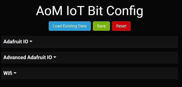
The GUI clarifies necessary credentials and preempts user pitfalls (discovered in user testing.) The basic Adafruit IO section allows users to quickly switch which pre-configured feed on the AoM cloud an IoT Bit points to without dealing with API keys. Our build works on Windows and Linux machines, but we're still working on making a functional Mac build. This is because OSX is a developmental nightmare. If you have a Mac and are an engineering student...why? You should have foreseen the pain that this causes you.


Finally...assembly. This involved:
-
Printing 8 new colored enclosures on our snazzy new Prusa printer
-
Soldering up 10 PCB shields
-
Creating 30 "Littlebits wire bit"-to-male header connections
-
Crimping 140 connections
-
Soldering 140 crimped wires to TUI peripherals
-
Embedding 40 threaded inserts in housings
-
Labeling 10 TUIs
-
Attaching decals & QR codes to all 10 housings
-
Creating a promotional video (credits to Oday Abushaban)
-
Prepping 10 SD cards with default credentials and GUI .exe files for credential changes
-
Testing and verifying all 10 IoT Bits
I had to enlist the help of ~15 fellow TA folk to assemble and verify 10 IoT Bits in 1 week, for which I am tremendously grateful. This offered a new challenge of communicating the assembly specifications to someone who had potentially never seen the "guts" of an IoT Bit before. On the right are some cable diagrams that I created to aid my assembly technicians.


Our hard work paid off. We deployed 10 units, one of which can be seen on the left with an orange housing. Many of our students used the IoT Bits, and 3 students ended up using one (or four!) IoT Bits in their final LittleBits project. I've included links to their project websites below:
We still had many mechanical issues/electrical connectivity issues. For REV 4 (which we hope to deploy in the Fall of 2023,) we will:
-
Ditch the Arduino and create one unified PCB, likely using an ESP32 chip. This will allow greater hardware flexibility and a smaller form factor.
-
Ditch the external TUI components. The LEDs, buttons, and switches will be directly connected to the PCB.
-
Ditch the 3D-printed housings. If everything is on one board, we can use that as a standalone unit.
-
Ditch Adafruit IO (which gives us loads of trouble) and replace it with our own backend.
-
Make the IoT Bits reconfigurable OTA.